EE3046微算機原理與實作 (Microcomputers Theory and Laboratory)
ICP (In-class
practice) Description
Part C. CPU Logic Circuit Design
|
|
||||||||||||||||||||||||||||||||||||||||||||||||||||||||
|
|
||||||||||||||||||||||||||||||||||||||||||||||||||||||||
|
Please finish Task 2 and 3, the
execution of Test Program 1 and 2. |
||||||||||||||||||||||||||||||||||||||||||||||||||||||||
|
|
||||||||||||||||||||||||||||||||||||||||||||||||||||||||
|
As instructed in the lecture, finish adding the instruction
decoding part to the circuit that you designed in last week. Test the
finished circuit by running the example program specified in the lecture.
|
||||||||||||||||||||||||||||||||||||||||||||||||||||||||
|
|
||||||||||||||||||||||||||||||||||||||||||||||||||||||||
|
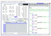
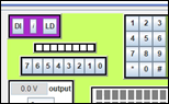
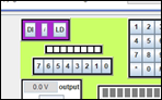
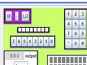
[ICP-C03-01] Practice microprogram design Design the microinstructions,
fill in µPM, and try out their execution in the dataPath
circuit that you designed in last week. Do this for the following
assembly instructions:
|
||||||||||||||||||||||||||||||||||||||||||||||||||||||||
|
|
||||||||||||||||||||||||||||||||||||||||||||||||||||||||
|
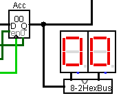
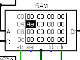
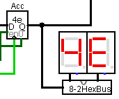
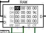
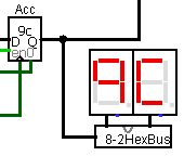
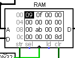
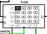
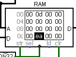
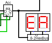
[ICP-C02-01] Practice data path design On the basis of the RAM and
ALU practice result of last week, design the data path of an 8051 CPU. Demonstrate the execution of
the following instruction sequence.
|
||||||||||||||||||||||||||||||||||||||||||||||||||||||||
|
|
||||||||||||||||||||||||||||||||||||||||||||||||||||||||
|
Build a simple ALU |
||||||||||||||||||||||||||||||||||||||||||||||||||||||||
|
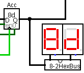
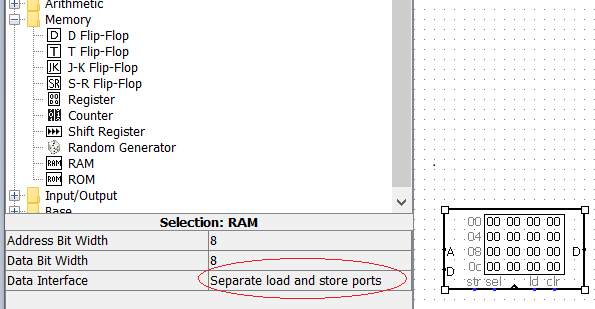
[ICP-C01-01] Practice using RAM with
"Separate load and store ports" |
||||||||||||||||||||||||||||||||||||||||||||||||||||||||
|
|

Part A. Assembly Programming
|
|
|
Program name: motor direction control with
simplified instruction sequence Learning object: To learn the operating
principle of motor control Function: The subroutine “setDirection” of Edsim51 Example 10 ( The motor.asm ) manages the motor direction control with many instructions,
as indicated in Hint. Please simplify this subrouitine so that it contains fewer instructions and
also make it more understandable. |
|
|
|
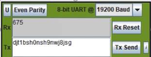
Program name: Transmit a numeral ASCII
after receiving it from serial input (at 19200 bps) Learning object: To learn the operating
principle of serial receiving and transmission Function: The processor
receives ASCII bytes from the UART. When a numeral ASCII byte is received,
the processor transmits the numeral ASCII byte back to the UART. Note:
First, test the program with no parity. After it works,
test it with odd and even parities. Video: |
|
[ICP-A07-01] Program name: Numeral test Learning object: To learn the encoding of
ASCII code Function: This program contains a subroutine called “numeralTest”. The subroutine tests whether the
accumulator contains the ASCII code of a numeral symbol (i.e., ‘0’, ‘1’, …, or ‘9’). Before return (i.e.,
RET), the subroutine sets the carry flag if it is numeral; otherwise, it
clears the carry flag. Video: |
|
|
|
Program name: Transmitting Data on the
8051 Serial Port - using Interrupt Learning object: To learn the operating
principle of serial transmission Function: The original Example 8 program uses
busy-waiting. In other words, it sends a byte to the serial port, then sits
in a loop (testing the TI flag) waiting for the serial port to say it's ready
for another byte. Now
please rewrite the program by making use of the serial port interrupt. |
|
[ICP-A06-01] Program name: Transmitting Data on the
8051 Serial Port – with odd parity Learning object: To learn the operating
principle of serial transmission Function: Rewrite Example 8 so that 8051 and the UART communicate with odd parity, instead of
even parity as in the original Example 8. Test the result with the UART device
selecting odd, no, and even parity, respectively. |
|
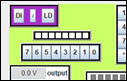
Program
name: keyPadScan
driven by a timer interrupt Learning object: To learn the operating
principle of keypad scanning and the timer interrupt Function: When you
execute this program, the main program will be constantly running to flash
the 8 LEDs. Meanwhile, it allows you to press the keypad at any time while
the main program is running. The keypad
scan is actually driven by a timer interrupt periodically every ??? ms. The key numbers of the pressed key will be
stored in a certain range of the RAM. |
|
[ICP-A05-02] Program
name: Scanning the keypad continuously and
storing the key number (without using interrupt) (preventing repeated
storing) Learning object: To learn the operating
principle of keypad scanning Function: This ICP is
to prevent repeated storing of the key number before a pressed key is
released, which can happen with ICP-A05-01. The repeated-storing
problem can be easily found if you set the “Update freq.” at 100 or higher.
In this ICP,
only once will a key number be stored into the RAM after the corresponding
key is pressed. Video: Video
note: Flag F0 indicates that some key is
pressed. Flag 2FH.0 indicates
that some key needs to been released. |
|
ICP-A05-01] ; Program
name: Scanning the keypad continuously and storing the key number (without
using interrupt) ; Learning
object: To learn the operating principle of keypad scanning ; Function:
; Example
7 stops after a key is pressed. however, in this ICP, the program won't stop. ; When
a key is pressed, the key number will be stored in the RAM and then the
program will keep scanning the keypad. ; The
RAM area that this program uses for storing the key numbers starts from
address 30H. |
|
|
|
Program
name: Interrupt to change rotation direction of
LED pattern Learning object: To learn the concept of
interrupt versus polling Function: Keep
showing a rotating pattern in the LED bar. The pattern maintains either left
rotation or right rotation. When an
external 0 interrupt occurs, the rotation direction will change from left
rotation to right rotation or from right rotation to left rotation. SW0 when closed will issue an
external 0 interrupt to the processor. Note: 『ICP-W04-prep - poll to change rotation direction of LED pattern.asm』doesn’t work well in changing the rotation
direction. Can you explain the reason.
How does ICP-W04-01 avoid this problem? Hint: ICP-W03-01 (Program name: Example 6 with INT 1 and Timer 1) exemplifies how to set up and use
the interrupt mechanism. Video: |
|
|
|
Program name: Example 6 with INT 1
and Timer 1 Learning object: To learn how to control the interrupt and the timer Function: This program functions the same way as Example 6 does. However, INT 1 and Timer 1 are used, instead of INT 0 and Timer 0. |
|
|
|
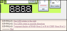
Program name: 7-segment display of
89AB (from L to R) & CDEF (from R to L) Learning object: To learn the coding of 0 to F for the 7-segment display Function: On 7-segment displays, show 8, 9, A, and B from left to right, and then show C, D, E, and F from right to left. Video: Note: Shown below are the hexadecimal number patterns of the 7-segment display:
View the 7-segment display code. |
|
[ICP-A02-02] Program name: Two
LEDs rotate in opposite directions Function: This program shows a combination of two patterns. One of the two pattern is to turn on only one LED from the leftmost to the rightmost LED. The other pattern is to turn on only one LED from the rightmost to the leftmost LED. Video: |
|
[ICP-A02-01] Program name: One LED rotates to the
right Function: This program shows an LED pattern in which only one LED lights up and it rotates to the right. Video: |
|
|